AREA MOMENTS OF INERTIA
- Second moment of area of a triangle
- Second moment of area of a ring
- Second moment of area of a rectangle
- Second moment of area of an I-beam
- Second moment of area of an L-beam
- Second moment of area of a C-beam
- Second moment of area of a T-Beam
- Moment of inertia of a rhombus
- Second moment of area of a hexagon
- Second moment of area about arbitrary axis
- Second moment of area of a two-rods beam
- Second moment of area of a three-rods beam
BEAM CALCULATORS
- Cantilever beam under concentrated load
- Beam with one end fixed and the other guided under concentrated load
- Beam with one end fixed and the other simply supported under concentrated load
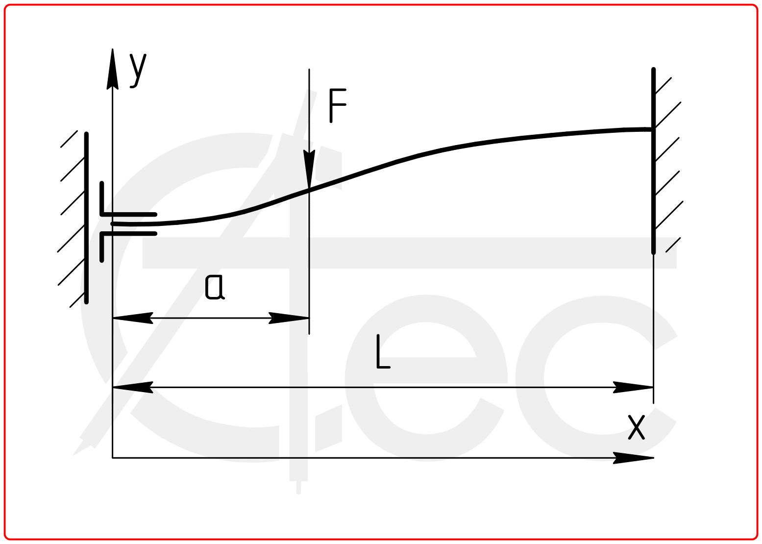
- Beam with both ends fixed under concentrated load
- Beam with both ends simply supported under concentrated load
- Beam with one end guided and the other simply supported under concentrated load
- Cantilever beam under distributed load
- Beam with one end fixed and the other guided under distributed load
- Beam with one end fixed and the other simply supported under distributed load
- Beam with both ends fixed under distributed load
- Beam with both ends simply supported under distributed load
- Beam with one end guided and the other simply supported under distributed load
TORSION OF BARS
- Bar of circular cross-section
- Bar of circular cross-section with a hole
- Bar of rectangular cross-section
- Thin-walled bar of rectangular cross-section
- Bar of triangular cross-section
- L-beam
- C-beam
- I-beam
- Thin-walled circular open tube
- Bar of an arbitrary cross section
- Shaft with keyway
- Split hollow shaft
CIRCULAR FLAT PLATES
- Circular plate with the outer edge simply supported
- Circular plate with outer edge simply supported and inner edge guided
- Circular plate with simply supported edges
- Circular plate with outer edge simply supported and inner edge fixed
- Circular plate with outer edge fixed
- Circular plate with outer edge fixed and inner edge guided
- Circular plate with outer edge fixed and inner edge simply supported
- Circular plate with fixed edges
- Circular plate with outer edge guided and inner edge simply supported
- Circular plate with outer edge guided and inner edge fixed
- Circular plate with inner edge simply supported
- Circular plate with inner edge fixed
BUCKLING
ELASTIC CONTACT
- Sphere and flat plate contact
- Two spheres contact
- Sphere and spherical socket contact
- Sphere and cylindrical socket contact
- Cylinder and flat plate contact
- Two parallel cylinders contact
- Cylinder and socket contact
- Two perpendicular cylinders contact
- General case of the two bodies in contact
- Knife-edge and the plate edge contact
- Rigid block and plate edge contact
- Cylinder end and flat plate contact
IMPACT LOADS
- Impact on a straight bar
- Impact on a conical bar
- Impact on a bar with combined cross section
- Impact of a bar on a rigid surface
- Impact on a beam with fixed ends
- Impact on a beam with simply supported ends
- Impact on a beam with fixed and hinge end
- Impact on a cantilever beam
- Visco-elastic model of Kelvin-Voigt on impact
NATURAL FREQUENCIES
- Cantilever beam
- Beam with simply supported ends
- Beam with fixed ends
- Beam with one end simply supported and the other end fixed
- Cantilever beam with concentrated mass
- Beam with simply supported ends and concentrated mass
- Beam with fixed ends and concentrated mass
- Simply supported beam with set of concentrated masses
- Circular plate with fixed edge
- Circular plate with simply spported edge
- Rectangular plate with fixed edges
- Rectangular plate with simply supported edges
PRESSURED SHELLS
- Pipe strength calculation
- Thin axisymmetric shells under internal pressure
- Thick-walled pipes under pressure and axial load
- Double-walled pipes
- Filled conical or cylindrical shell
- Toroidal shell under pressure
- Corrugated tube under axial load
- Tube under external concentrated load
- Tube under linearly distributed uniform load
FLUID DYNAMIC
- Uncompressible fluid flow in pipeline
- Gas flow in pipeline
- Cavitation
- Water hammer in pipeline
- Flow velocity profile in pipeline
- Fluid flow in an open channel
- Fluid flow through the nozzles
- Fluid flow under surface level
- Fluid outflow from a vessel
- Calculation of flow rate of weir spillway
- Jet pressure on surface
- Jet height calculation
COMPOSITES
SPRINGS
THREAD CONNECTIONS
- Metric thread tightening torque
- Inch thread tightening torque
- Flange connection tightening force
- Bolted connection tightening force
- Bracket bolts under bending load
- Bracket bolts under torsion load
- Bolt tightening of a shaft mounted lever
- Bolt tightening of a bar mounted clamp
- One-bolt clamp tightening
- Two-bolt clamp tightening
- Tightening force of a two-bolt clamp under axial load
- Taper connection tightening force
SHAFT CONNECTIONS
BEARINGS
FATIGUE
HEAT TRANSFER
- Natural convection for horizontal surface
- Natural convection for vertical surface
- Convection film coefficient of a flat wall
- Convection film coefficient of internal pipe surface
- Convection film coefficient of external pipe surface
- Convection film coefficient of tube bundle
- Heat transfer through flat wall
- Heat transfer through tube wall